How to Install Ethernet Cable
Tips for Installing Data Cables
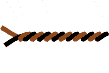
Twisting Ethernet CAT Cable


Try to minimize the amount of jacket twisting. If the cable is over-twisted, it can lead to torn jackets.
Ethernet Cable Termination

Make sure every twisted pair cable maintains its pair twisting to within 1/2" or less of the point of termination on the connecting hardware. Any
untwisting of pairs greater than this will adversely affect the performance of the cable and reduce its ability to transmit at full, effective speeds.
Cable Runs Tips
Cables in Conduit
Never run data cables in the same conduit as electrical wiring.
Home Run Cable
Home run cable where possible to maximize data transmission.
Cable Tension
When pulling cable, avoid kinking and tugging. Constant tension should be used when pulling cable into place.
EIA/TIA-568A specifies a maximum pulling tension of 25 pounds for CAT cable installation.
Cable Length
Plan out your installation so that you do not run cable further than 90m (295').
For Ethernet Cat5 Patch cables -- ANSI/TIA/EIA 568A allows for a maximum patch cable length of 6m (20') in the wiring
closet and 3m (10') at the workstation outlet. If either of these lengths is exceeded, reduce the horizontal cable run by the excess amount.
Miscellaneous Tips
Prevent Crosstalk
Many networks that run on UTP ethernet cable use only two of the four pairs of wires. To prevent crosstalk, do not use the second
unused pair for voice or other data applications.
Reduce Interference
When routing cables through walls and ceilings, always keep data cable as far away as possible from sources of EMI
(electromagnetic interference) and RFI (radio frequency interference), such as fluorescent lights, electric panels, light dimmers, and electrical motors.
Route Cable Safely
Avoid routing ethernet cables through areas with excess heat and areas that are exposed to moisture because those conditions
may cause attenuation problems.
Use Stranded Conductors
Patch cables are intended to be flexed and moved, so stranded conductor patch cords are recommended because of
their flexibility over solid conductors.
Basic Topologies for Data Cable Installation
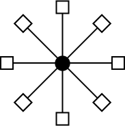
Star Topology

A star topology setup utilizes a central point of control. Each station or device in the telecommunications system communicates point-to-point wiring to
this central link. In most situations, address recognition is the responsibility of the central control point, which then, directs the information to the
cabling path of the device associated with that address. A star topology is considered the easiest to design and install since each station's cabling
is run directly out from the central location to the appropriate work area. It is also adaptable to other topologies.
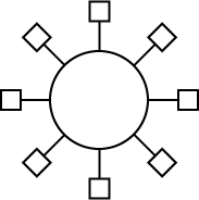
Ring Topology

A ring topology is structured with stations cabled together in a logical circle. Information travels in one direction passing through each station and only stopping
at the addressed station. Only one station can transmit on the ring at any one time. Stations take turns gaining access to the ring via polling or
by passing an access token from one to another.
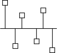
Bus Topology

A bus topology setup has all the devices attached to a linear transmission media. When a station transmits, the signal travels in both directions. Signals traveling
along the bus are made available to all stations. Each station checks the intended address of the signal and ignores all information not addressed
to its location.
Browse Our Cables, Accessories, and Tools
Other Helpful Cable Reference Guides:
Warning: When using this information to perform electrical work, call a licensed electrician and consult the NEC® for safety.
All licensed electricians have passed examinations covering the National Electric Code®, know state and
local building codes, and may carry insurance to cover damages.